Centrifugal Force
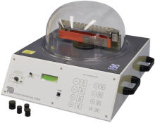
Demonstrates the relationship between centrifugal force, radius and velocity of rotating masses.
TecQuipment’s Whirling of Shafts and Critical Speed apparatus (TM1001) shows how shafts vibrate transversely and ‘whirl’ at a certain rotation frequency. This helps engineers understand possible problems with long shafts and allow for them in their designs.
The equipment is in two parts and fits on a bench or desktop. The main part is a solid alloy frame that holds a variable speed motor which turns the horizontal test shaft. Two bearings hold the shaft, one bearing at the ‘driven end’ and the other bearing at the ‘tail end’ of the shaft. The tail end bearing slides in its housing to allow the shaft length to change as it ‘whirls’. Similar to a beam on two simple knife-edge supports, both bearings allow free angular shaft movement (free ends condition). Also supplied with the equipment are extra bearings that restrict angular movement when fitted, to give ‘fixed ends’.
Two movable nylon bushes help to prevent the shaft whirling amplitude from reaching excessive levels. A movable cord plate allows students to control the shaft in some experiments, to help reach the second mode whirl speed. A sensor at the driven end measures the shaft speed and sends its signal to the Control and Instrumentation Unit display. A removable safety guard with magnetic interlock surrounds the shaft and only allows the motor to work when fitted.
The separate Control and Instrumentation Unit contains the drive for the variable speed motor and a display to show the shaft speed. It also includes a trigger output for the optional stroboscope.
When used in a darkened classroom, the optional stroboscope gives an impressive demonstration of how the shaft shape changes as it reaches its whirling speeds. Supplied with the apparatus is a set of test shafts of different length and diameter to show how these properties affect whirling and its ‘critical speed’. Also supplied is a set of weights to show how concentrated loads affect whirling. One weight has an extra hole to make it an eccentric load. This helps to show the phase difference between the load and the deflection (you need the optional stroboscope to see this clearly).

Demonstrates the relationship between centrifugal force, radius and velocity of rotating masses.
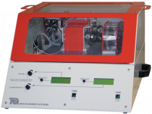
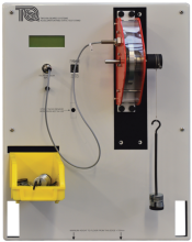
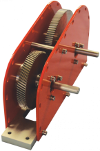

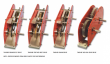
An experimental unit to allow students to find the dynamic efficiency of various drive types. The unit comes complete with a gear drive unit which can be configured as a simple or compound drive.
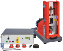
A bench-mounted apparatus and control and instrumentation unit, for studying the dynamic behavior of different cams and followers and their 'bounce' speed.
