2 DOF Robot

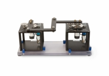
The 2 DOF Robot module is ideal to introduce students to the fundamental and intermediate principles of robotics. You can use it to demonstrate real-world control challenges, such as pick-and-place robots used in manufacturing lines.
The Active Suspension Experiment teaches cutting-edge technology that has brought a new generation of vehicles to life.
Active suspension technology is used in the automotive industry to continuously control the vertical movement of the vehicle wheel using an actively-controlled actuator placed on the suspension axis. Similar technologies have also been used in train bogies to improve the curving behavior of the train and the decreased acceleration perceived by the passenger.
The Active Suspension consists of three masses that along stainless steel shafts using linear bearings and is supported by a set of springs. The upper mass (blue) represents the vehicle body supported above the suspension, the middle mass (red) corresponds to one of the vehicle’s tires, and the bottom (silver) mass simulates the road. The upper mass is connected to a high-quality DC motor through a capstan to emulate an active suspension system that can dynamically compensate for the motions introduced by the road. The lower plate is driven by a powerful DC motor connected to a lead screw and cable transmission system.
The following additional components are required to complete your workstation, and are sold separately:

The 2 DOF Robot module is ideal to introduce students to the fundamental and intermediate principles of robotics. You can use it to demonstrate real-world control challenges, such as pick-and-place robots used in manufacturing lines.

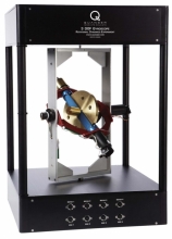
The principles demonstrated by the Quanser 3 DOF Gyroscope are relevant in technologies used to control orientation in sea, air and space vehicles.

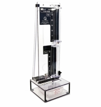
The Coupled Tanks system is a process control experiment ideal for teaching and research of control topics related to liquid level control.
