Coriolis Force


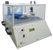
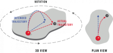
A highly visual demonstration of the Coriolis Force on a jet of water.
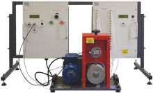
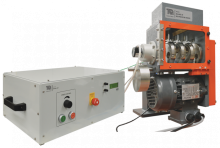
A bench-mounting base unit forms the main part of this set of products. Supplied with a three-shaft gear drive unit as standard, the base unit dynamically tests the gear drive and the other optional drive units (TM1018b, c and d). The dynamic tests run the input of the different drive units at a given speed using a motor while measuring the input power. At the same time, a dynamometer loads the output of the drive unit while measuring the output power. Students use the measurements to find the performance and efficiency of the drive unit.
Students may set the gear unit (supplied) as a simple or compound drive by sliding a gear in or out of mesh on the third shaft.
Includes simple tools needed to fit the drive units to the base unit, and to adjust the compound gear drive.
In the base unit’s upper level, the student fits their choice of a drive unit. A variable-speed, low-voltage motor provides the shaft input turning force (effort) to the drive. A dynamometer provides the output braking force (load) to the drive. The dynamometer uses electromagnetic braking and a hysteresis effect to provide a variable load at a constant torque irrespective of the speed. Sensors on the motor and dynamometer measure their shaft speed, torque and therefore power in and out at the drive. Fans provide air cooling for both the motor and dynamometer. Flexible couplings with collets connect the drive unit to the motor and dynamometer for quick and accurate alignment.
Axial trunnions with race bearings hold the motor and the dynamometer for free rotation against their load cell sensors to measure torque accurately.
On the base unit’s lower level, controls, and microprocessor-controlled multi-line displays adjust the motor speed and the load while showing measurements of torque, speed, and power.
The base unit’s upper level includes an interlocked guard with transparent sections to prevent students from touching any moving parts while allowing them to see what is happening.
You can do tests with or without a computer connected. However, for quicker tests with an easier recording of results, TecQuipment can supply the optional Versatile Data Acquisition System (VDAS®). This gives accurate real-time data capture, monitoring and display, calculation and charting of all the important readings on a computer.
A separate ‘Acceleration and Static Test Stand’ (TM1018a) gives extra experiments in measuring angular acceleration and static efficiency. You may use clamps to mount the Test Stand temporarily on the edge of a desk, but TecQuipment recommends a more permanent fixing to the desk or to a wall.
The test stand includes sets of weights to apply turning forces to the shaft of a flywheel (included as standard) or the gear drive from the TM1018. A sensor and a multiline display automatically calculate angular acceleration. Students use this to find inertia by experiment.
The flywheel forms a simplified version of one of the gears in the gear drive, to provide a starting point in understanding inertia calculations of more complex gear drives. The test stand also allows simple static efficiency tests on the gear drive for comparison with those from dynamic tests on the base unit. A slot to the front of the test stand holds a tray (supplied) to store your weights and other loose items.
The optional drive units work with the TM1018 base unit for dynamic tests on performance, allowing comparison with the gear drive. For extended experiments, the optional drives each include three diff erent methods of adjusting their tension to show how this aff ects performance. The three methods include:
With each drive unit, TecQuipment supplies a tension spring and a spring balance to set the tension of the tension pulley.
The shafts of all drive units run on maintenance-free, lowfriction ball races.
The optional drive units work with the TM1018 base unit for dynamic tests on performance, allowing comparison with the gear drive. For extended experiments, the optional drives each include three different methods of adjusting their tension to show how this affects performance. The three methods include:
With each drive unit, TecQuipment supplies a tension spring and a spring balance to set the tension of the tension pulley.
The shafts of all drive units run on maintenance-free, lowfriction ball races.


A highly visual demonstration of the Coriolis Force on a jet of water.

Bench mounted, self contained air bearing apparatus to demonstrate the performance of self acting, gas lubricated journal bearings, including the phenomenon of half speed whirl.

A bench-mounted model four-cylinder engine with control and instrumentation unit that demonstrates the primary and secondary forces and moments when balancing reciprocating masses.
